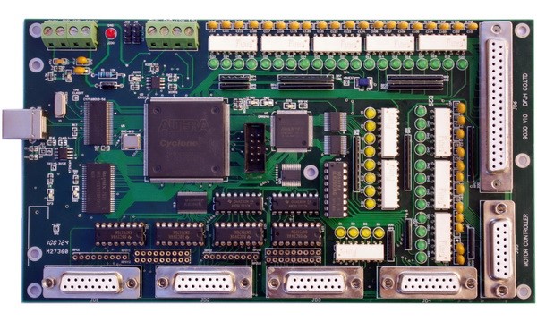
Each axis of 9030 card can work in two modes: open_loop mode and semi_closed_loop. in these two modes, 9030 card all outputs pulse. Must connect the encoder signals to the 9030 card when it works under semi_closed loop mode.

| Name | direction | definition |
| A- | in | Encoder Phase A- |
| A+ | in | Encoder Phase A+ |
| B- | in | Encoder Phase B- |
| B+ | in | Encoder Phase B+ |
| Z- | in | Encoder Phase Z- |
| Z+ | in | Encoder Phase Z+ |
| +5V | out | +5V Power |
| PLUS | out | Output pulse CW/Pulse+ |
| /PLUS | out | Output pulse CW/Pulse- |
| SIGN | out | Output pulse CCW/DIR+ |
| /SIGN | out | Output pulse CCW/DIR- |
| ALM | in | Alarm input |
| GND | Gnd | |
| SVon | output | Servo_on output |
| SV COM | Servo_on common GND | Servo_on common GND |
| shield | shield(GND) |
| Name | Definition | Explain |
| 1 | A+ | MPG Phase A+ |
| 9 | A- | MPG Phase A- (unplug when Single-ended encoder input) |
| 2 | B+ | MPG Phase B+ |
| 10 | B- | MPG Phase B- (unplug when Single-ended encoder input) |
| 3 | GND | |
| 11 | +5V | |
| 4 | I25(REV) | GPI |
| 12 | I26(Xsel) | GPI (X axis selected , defined in WinCNC) |
| 5 | I27(Ysel) | GPI (Y axis selected , defined in WinCNC) |
| 13 | I28(Zsel) | GPI (Z axis selected , defined in WinCNC) |
| 6 | I29(Wsel) | GPI (W axis selected , defined in WinCNC) |
| 14 | I30(Multi×1) | GPI(pulse×1, defined in WinCNC)) |
| 7 | I31(Multi×10) | GPI(pulse×10, defined in WinCNC)) |
| 15 | I32(Multi×100) | GPI(pulse×100, defined in WinCNC)) |
| 8 | GND |
